


DR 540 :
9 kHz - 400 MHz / 540 W CW
- Class A solid state
- Broadband (instantaneous single band): 9 kHz –400 MHz
- Frequency extension between 4 kHz and 9 kHz upon request
- Typical output power : 540 W CW
-
Linear output power (1 dB compression) guaranted with harmonics <-20 dBc:
- P1dB > 300 W and H<-20 dBc up to 250 MHz and
- P1dB > 150 W and H<-20 dBc from 250 MHz to 400 MHz
- Air cooling: self contained fans
- Can operate in full mismatch conditions without damage
- Reliable, efficient and robust
- 19" Rack
- 3 years standard warranty
VERSIONS :
-
DR 540 D amplifier with:
- Multicolor LCD display with touch panel
- Digital control
- IEEE 488 GPIB, Ethernet, USB, RS232 Communications
- Temperature controlled fans
- Safety interlock
-
DR 540 DC : DR 540 D with :
- Integrated dual directional coupler
- display of instantaneous incident and reflected power
MAINTENANCE :
-
Amplifier designed for minimal maintenance
- Easy access to all parts
- Modular design
- Repairs with minimum adjustments
- Rapid diagnostic
- Minimal downtime
- Contract for preventive and corrective maintenance available
APPLICATIONS :
- EMC tests
- RF tests and instrumentation
- Radiocommunication
- Measurement and research laboratories
- Frequency bandwidth : 9 kHz - 400 MHz
- Typical output power : 540 W
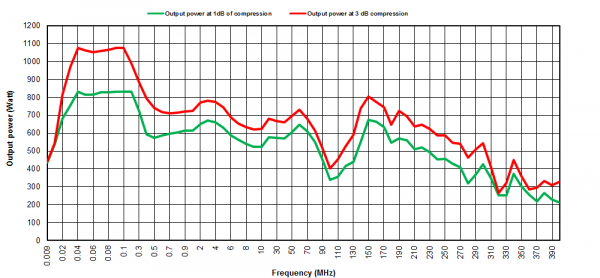
- Power at 3 dB compression : 350 W min. up to 250 MHz / 250 W min. from 250 MHz to 400 MHz
- Power at 1 dB compression : 300 W min. up to 250 MHz / 150 W min. from 250 MHz to 400 MHz
- Harmonics distortion : H2,H3 < -20 dBc for the output power at 1 dB compression limit
- Class type : Class A
- Gain : 52 dB
- Linear power gain flatness : ± 2.5 dB max
- Mismatch tolerance : infinite without damage
- Input impedance : 50 ohms / VSWR: 2:1max
- Output impedance : 50 ohms / VSWR: 2:1max
- Input power : +10 dBm max.
- RF input connector : Type N fem. (front or rear panel) – other connector type on request
- RF output connector : Type N fem. (front or rear panel) – other connector type on request
- Safety interlock : Connector type BNC
- Digital control : Transistors, power supplies, temperatures, fans
- Communication interface : Ethernet, USB, GPIB, RS232
- Color LCD Display with touch screen : Status, faults, (direct and reverse instantaneous power for DC version)
- Ambient operating temperature : 0 °C / + 35 °C
- Room temperature storage : -20 °C / +70 °C
- Cooling : Forced air with fan speed control: 120 l/sec max. (self contained fans)
- Power voltage : 200-250 VAC, 47-63 Hz, single phase
- Rated current : 10.9 A at 230 VAC
- Dimensions : 640 x 450 x 360 mm (8U) / 25.2 x 17.7 x 14.2 in (8U)
- Weight : 51 kg / 112 lb
DR 540 DC version :
- Integrated bidirectional power coupler : Coupling factor 49 dB typ.
- Power coupling connector : Type N fem. (rear panel)
- Estimated output power losses due to the coupler : 0.3 dB
- External coupler
- Supply and integration inside a cabinet
- Bulk Current Injection + Calibration JIG
- RF Power cable
- Switching unit

